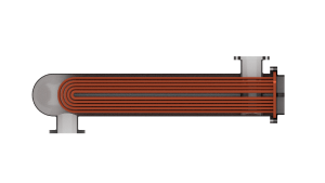
Specific Dissipation Heat Exchanger (TL-TL)
Heat exchanger parameterized by specific dissipation data for systems with two thermal liquid flows
Since R2024a

Libraries:
Simscape /
Fluids /
Heat Exchangers /
Thermal Liquid
Description
The Specific Dissipation Heat Exchanger (TL-TL) block models the complementary cooling and heating of fluids held briefly in thermal contact across a thin conductive wall. The block uses a simplified model based on the concept of specific dissipation, which is a measure of the heat transfer rate.
Heat Transfer Model
The block heat transfer model depends on the heat transfer rate defined by the specific dissipation. Specific dissipation is a measure of the heat transfer rate observed when thermal liquid 1 and thermal liquid 2 inlet temperatures differ by one degree. Its product with the inlet temperature difference gives the expected heat transfer rate
where ξ is specific dissipation and
TIn is inlet temperature for
thermal liquid 1 (subscript 1) or thermal liquid 2 (subscript
2). The specific dissipation is a tabulated function of the
mass flow rates into the exchanger through the thermal liquid 1 and thermal liquid 2 inlets:
To accommodate reverse flows, the tabulated data can extend over positive and negative flow rates, in which case the inlets can also be thought of as outlets. The data normally derives from measurement of heat transfer rate against temperature in a real prototype:
The heat transfer model, as it relies almost entirely on tabulated data, and as that data normally derives from experiment, requires little detail about the exchanger. Flow arrangement, mixing condition, and number of shell or tube passes, if relevant to the heat exchanger modeled, are assumed to manifest entirely in the tabulated data.
See the Specific Dissipation Heat Transfer block for more detail on the heat transfer calculations.
Composite Structure
The block is a composite component. A Specific Dissipation Heat Exchanger Interface (TL) block models the thermal liquid flow on side 1 of the heat exchanger. Another models the thermal liquid flow on side 2. A Specific Dissipation Heat Transfer block captures the heat exchanged across the wall between the flows.


Ports
Conserving
Parameters
Extended Capabilities
Version History
Introduced in R2024aYou can also select a web site from the following list:
Americas
- América Latina (Español)
- Canada (English)
- United States (English)
Europe
- Belgium (English)
- Denmark (English)
- Deutschland (Deutsch)
- España (Español)
- Finland (English)
- France (Français)
- Ireland (English)
- Italia (Italiano)
- Luxembourg (English)
- Netherlands (English)
- Norway (English)
- Österreich (Deutsch)
- Portugal (English)
- Sweden (English)
- Switzerland
- United Kingdom (English)