Spring-Loaded Accumulator
(To be removed) Hydraulic accumulator with spring used for energy storage
The Hydraulics (Isothermal) library will be removed in a future release. Use the Isothermal Liquid library instead. (since R2020a)
For more information on updating your models, see Upgrading Hydraulic Models to Use Isothermal Liquid Blocks.
Library
Accumulators
Description
This block models a spring-loaded hydraulic fluid accumulator. The accumulator consists of a preloaded spring and a fluid chamber. The fluid chamber is connected to a hydraulic system.
As the fluid pressure at the accumulator inlet becomes greater than the preload pressure, fluid enters the accumulator and compresses the spring, storing hydraulic energy. A decrease in the fluid pressure causes the spring to decompress and discharge stored fluid into the system.
During typical operations, the spring pressure is equal to the pressure in the fluid chamber. However, if the pressure at the accumulator inlet drops below the preload pressure, the spring becomes isolated from the system. In this situation, the fluid chamber is empty and the spring pressure remains constant and equal to the preload pressure while the pressure at the accumulator inlet depends on the hydraulic system to which the accumulator is connected. If the pressure at the accumulator inlet builds up to the preload pressure or higher, fluid enters the accumulator again.
The motion of the spring is restricted by two hard stops that limit the expansion and contraction of the fluid volume. The fluid volume is limited when the fluid chamber is at capacity and when the fluid chamber is empty. The hard stops are modeled with finite stiffness and damping. This means that it is possible for the fluid volume to become negative or greater than the fluid chamber capacity, depending on the values of the hard-stop stiffness coefficient and the accumulator inlet pressure.
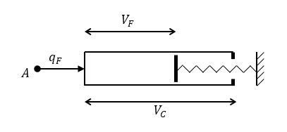
The diagram represents a spring-loaded accumulator. The fluid chamber is on the left and the spring is on the right. The distance between the left side and the spring defines the fluid volume (VF).
The hard stop contact pressure is modeled with a stiffness term and a damping term. The accumulator spring is assumed to have a linear relationship between the spring pressure and the fluid volume, with pressure balanced at the end of the spring:
where
| VF | Volume of fluid in the accumulator |
| Vinit | Initial volume of fluid in the accumulator |
| VC | Fluid chamber capacity |
| pF | Pressure at the accumulator inlet (gauge) |
| ppr | Preload pressure (gauge) |
| Kspr | Spring gain coefficient |
| pmax | Pressure needed to fully fill the accumulator |
| pspr | Pressure developed by the spring |
| pHS | Hard-stop contact pressure |
| Ks | Hard-stop stiffness coefficient |
| Kd | Hard-stop damping coefficient |
| qF | Fluid flow rate into the accumulator, which is positive if fluid flows into the accumulator |
The flow rate into the accumulator is the rate of change of the fluid volume:
At t = 0, the initial condition is VF = Vinit, where Vinit is the value you assign to the Initial fluid volume parameter.
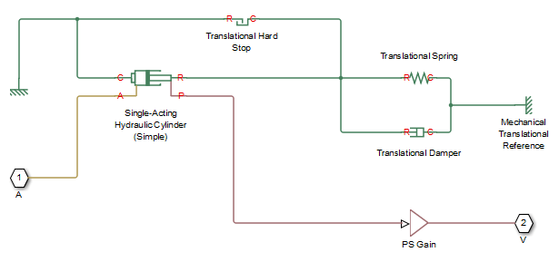
The Spring-Loaded Accumulator block does not consider loading on the separator. To model additional effects, such as the separator inertia and friction, you can construct a spring-loaded accumulator as a subsystem or a composite component, similar to the block diagram below.
Variables
To set the priority and initial target values for the block variables prior to simulation, use the Initial Targets section in the block dialog box or Property Inspector. For more information, see Set Priority and Initial Target for Block Variables.
Nominal values provide a way to specify the expected magnitude of a variable in a model. Using system scaling based on nominal values increases the simulation robustness. Nominal values can come from different sources, one of which is the Nominal Values section in the block dialog box or Property Inspector. For more information, see Modify Nominal Values for a Block Variable.
Basic Assumptions and Limitations
The accumulator spring is assumed to be behave linearly.
Loading on the separator, such as inertia or friction, is not considered.
Inlet hydraulic resistance is not considered.
Fluid compressibility is not considered.
Parameters
Parameters Tab
- Fluid chamber capacity
Amount of fluid that the accumulator can hold. The default value is
8e-3m^3.- Preload pressure (gauge)
Spring pressure (gauge) when the fluid chamber is empty. The default value is
10e5Pa.- Pressure at full capacity (gauge)
Spring pressure (gauge) when the fluid chamber is at capacity. The default value is
30e5Pa.- Hard-stop stiffness coefficient
Proportionality constant of the hard-stop contact pressure with respect to the fluid volume penetrated into the hard stop. The hard stops are used to restrict the fluid volume between zero and fluid chamber capacity. The default value is
1e10Pa/m^3.- Hard-stop damping coefficient
Proportionality constant of the hard-stop contact pressure with respect to the flow rate and the fluid volume penetrated into the hard stop. The hard stops are used to restrict the fluid volume between zero and fluid chamber capacity. The default value is
1e10Pa*s/m^6.
Ports
The block has one hydraulic conserving port associated with the accumulator inlet.
The flow rate is positive if fluid flows into the accumulator.
Extended Capabilities
Version History
Introduced in R2006aSee Also
You can also select a web site from the following list:
Americas
- América Latina (Español)
- Canada (English)
- United States (English)
Europe
- Belgium (English)
- Denmark (English)
- Deutschland (Deutsch)
- España (Español)
- Finland (English)
- France (Français)
- Ireland (English)
- Italia (Italiano)
- Luxembourg (English)
- Netherlands (English)
- Norway (English)
- Österreich (Deutsch)
- Portugal (English)
- Sweden (English)
- Switzerland
- United Kingdom (English)