Linearize Pulp Paper Process Model
This example shows how to linearize a process model at a steady-state operating point.
Thermo-mechanical pulping (TMP) is a process for producing mechanical pulp for newsprint. In this example, you use a typical process arrangement for a two-stage TMP operation:
In the first stage, the primary refiner produces a course pulp from a feed of wood chips and water.
In the second stage, the secondary refiner further develops the pulp bonding properties so that it is suitable for paper making.
Each refiner consists of two disks with overlaid grooved surfaces. When in operation, either the two disks rotate in opposite directions or one disk rotates while the other disk remains stationary.
The disk surfaces physically impact on a three-phase flow of wood fibers, steam, and water that passes from the center of the refiner disks to their periphery. The physical impact of the disk surfaces on the wood fibers:
Breaks rigid chemical and physical bonds between the fibers
Microscopically roughens the surface of individual fibers enabling them to mesh together on the paper sheet.
The primary objective of controlling the TMP plant is to apply sufficient energy to derive pulp with good physical properties without incurring excess energy costs or fiber damage due to the imposition of overly high stresses as fibers pass through the refiners. For practical purposes, this objective amounts to controlling the ratio of the total electrical energy applied by the two refiners to the dry mass flow rate of wood fibers, that is, controlling the estimated specific energy applied to the pulp.
A secondary control objective is to control the pulp consistency, that is the ratio of dry mass flow rate (fibers) to overall mass flow rate (water & fibers), to a value which optimizes a trade-off between energy consumption and pulp quality.
The TMP process has the following inputs.
Feed rate of chips (Feed rpm)
Dilution water flow to each of the refiners (Primary and secondary dilution setpoints)
Setpoints to two regulatory controllers which control the gap between the rotating disks in each set of refiners.
The TMP process has the following outputs.
Primary and secondary refiner consistencies
Primary and secondary refiner motor loads
Vibration monitor measurements for the two refiners
Open the scdtmp model, which implements the thermo-mechanical pulping process.
mdl = 'scdtmp';
open_system(mdl)
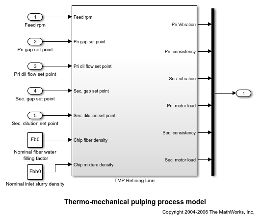
In this example, your goal is to find a linear model of this system at a steady-state operating condition for the following input setpoint conditions.
Feed Rate = 30
Primary Gap = 0.8
Primary Dilution = 170
Secondary Gap = 0.5
Secondary Dilution = 120
Find Operating Points
To find the operating point, first create an operating point specification object using the operspec function.
opspec = operspec(mdl)
opspec =


 Operating point specification for the Model scdtmp.
 (Time-Varying Components Evaluated at time t=0)

States:
----------
     x         Known    SteadyState     Min         Max        dxMin       dxMax
___________ ___________ ___________ ___________ ___________ ___________ ___________

(1.) scdtmp/TMP Refining Line/Fiber fill dynamics/Internal
  3.5556       false       true        -Inf         Inf        -Inf         Inf
(2.) scdtmp/TMP Refining Line/Fiber water fill dynamics/Internal
  6.8283       false       true        -Inf         Inf        -Inf         Inf
(3.) scdtmp/TMP Refining Line/Primary dilution/Internal
    170        false       true        -Inf         Inf        -Inf         Inf
(4.) scdtmp/TMP Refining Line/Primary plate gap/Internal
    0.8        false       true        -Inf         Inf        -Inf         Inf
(5.) scdtmp/TMP Refining Line/Primary refiner motor/LTI System/Internal
    8.5        false       true        -Inf         Inf        -Inf         Inf
(6.) scdtmp/TMP Refining Line/Primary screw feeder/Internal
    30         false       true        -Inf         Inf        -Inf         Inf
(7.) scdtmp/TMP Refining Line/Sec refiner motor/LTI System/Internal
    6.7        false       true        -Inf         Inf        -Inf         Inf
(8.) scdtmp/TMP Refining Line/Secondary dilution/Internal
    0.5        false       true        -Inf         Inf        -Inf         Inf
(9.) scdtmp/TMP Refining Line/Secondary plate gap/Internal
    0.5        false       true        -Inf         Inf        -Inf         Inf

Inputs:
----------
  u   Known  Min   Max
_____ _____ _____ _____

(1.) scdtmp/Feed rpm
  0   false -Inf   Inf
(2.) scdtmp/Pri gap set point
  0   false -Inf   Inf
(3.) scdtmp/Pri dil flow set point
  0   false -Inf   Inf
(4.) scdtmp/Sec. gap set point
  0   false -Inf   Inf
(5.) scdtmp/Sec. dilution set point
  0   false -Inf   Inf

Outputs:
----------
  y   Known  Min   Max
_____ _____ _____ _____

(1.) scdtmp/Out1
  0   false -Inf   Inf
  0   false -Inf   Inf
  0   false -Inf   Inf
  0   false -Inf   Inf
  0   false -Inf   Inf
  0   false -Inf   Inf
Specify the feed rate input value and indicate that this value is known.
opspec.Inputs(1).u = 30;
opspec.Inputs(1).Known = 1;
Similarly, specify the known primary gap setpoint.
opspec.Inputs(2).u = 0.8;
opspec.Inputs(2).Known = 1;
Specify the known primary dilution setpoint.
opspec.Inputs(3).u = 170;
opspec.Inputs(3).Known = 1;
Specify the known secondary gap setpoint.
opspec.Inputs(4).u = 0.5;
opspec.Inputs(4).Known = 1;
Specify the known secondary dilution setpoint.
opspec.Inputs(5).u = 120;
opspec.Inputs(5).Known = 1;
Trim the model for the given operating point specifications using the findop function.
op = findop(mdl,opspec);
 Operating point search report:
---------------------------------

opreport =


 Operating point search report for the Model scdtmp.
 (Time-Varying Components Evaluated at time t=0)

Operating point specifications were successfully met.
States:
----------
   Min         x         Max       dxMin        dx       dxMax
__________ __________ __________ __________ __________ __________

(1.) scdtmp/TMP Refining Line/Fiber fill dynamics/Internal
   -Inf      3.5556      Inf         0          0          0
(2.) scdtmp/TMP Refining Line/Fiber water fill dynamics/Internal
   -Inf      6.8283      Inf         0          0          0
(3.) scdtmp/TMP Refining Line/Primary dilution/Internal
   -Inf       170        Inf         0          0          0
(4.) scdtmp/TMP Refining Line/Primary plate gap/Internal
   -Inf       0.8        Inf         0          0          0
(5.) scdtmp/TMP Refining Line/Primary refiner motor/LTI System/Internal
   -Inf      8.4952      Inf         0          0          0
(6.) scdtmp/TMP Refining Line/Primary screw feeder/Internal
   -Inf        30        Inf         0          0          0
(7.) scdtmp/TMP Refining Line/Sec refiner motor/LTI System/Internal
   -Inf      6.6385      Inf         0      1.7355e-12     0
(8.) scdtmp/TMP Refining Line/Secondary dilution/Internal
   -Inf       120        Inf         0          0          0
(9.) scdtmp/TMP Refining Line/Secondary plate gap/Internal
   -Inf       0.5        Inf         0          0          0

Inputs:
----------
Min  u  Max
___ ___ ___

(1.) scdtmp/Feed rpm
30  30  30
(2.) scdtmp/Pri gap set point
0.8 0.8 0.8
(3.) scdtmp/Pri dil flow set point
170 170 170
(4.) scdtmp/Sec. gap set point
0.5 0.5 0.5
(5.) scdtmp/Sec. dilution set point
120 120 120

Outputs:
----------
  Min       y       Max
________ ________ ________

(1.) scdtmp/Out1
  -Inf   0.026027   Inf
  -Inf   0.39991    Inf
  -Inf   0.56757    Inf
  -Inf    8.4952    Inf
  -Inf   0.34914    Inf
  -Inf    6.6385    Inf
Linearize Model
To linearize the model, first define the linearization input and output points.
For this example, use the following input points.
Feed rate
Primary gap
Primary dilution
Secondary gap
Secondary dilution
io(1) = linio('scdtmp/Feed rpm',1,'input');
io(2) = linio('scdtmp/Pri gap set point',1,'input');
io(3) = linio('scdtmp/Pri dil flow set point',1,'input');
io(4) = linio('scdtmp/Sec. gap set point',1,'input');
io(5) = linio('scdtmp/Sec. dilution set point',1,'input');
The output of the Mux block contains the six model outputs in the following order.
Primary vibration
Primary consistency
Secondary vibration
Primary motor load
Secondary consistency
Secondary motor load
io(6) = linio('scdtmp/Mux',1,'output');
Linearize the model at the computed steady-state operating point.
sys = linearize(mdl,op,io);
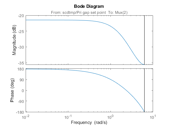
You can view the response for the resulting linear system from any input to any output. For example, plot the Bode response between the primary gap setpoint and the primary consistency.
bode(sys(2,2))
See Also
operspec | findop | linio | linearize
Related Topics
You can also select a web site from the following list:
Americas
- América Latina (Español)
- Canada (English)
- United States (English)
Europe
- Belgium (English)
- Denmark (English)
- Deutschland (Deutsch)
- España (Español)
- Finland (English)
- France (Français)
- Ireland (English)
- Italia (Italiano)
- Luxembourg (English)
- Netherlands (English)
- Norway (English)
- Österreich (Deutsch)
- Portugal (English)
- Sweden (English)
- Switzerland
- United Kingdom (English)